The Impatient Programmer's Guide to Bevy and Rust: Chapter 2 - Let There Be a World
Here’s what you will be able to achieve by the end of this tutorial.
Procedural Generation
I respect artists who hand craft tiles to build game worlds. But I belong to the impatient/lazy species.
I went on an exploration and came across procedural generation.
Little did I know the complexities involved. I was in the verge of giving up, however because of the comments and messages from readers of chapter 1, I kept going. And the enlightment came three days ago, all the pieces fit together.
Basically it’s about automatically fitting things together like a jigsaw puzzle. To solve this problem, let’s again think in systems.
What do we need to generate the game world procedurally?
- Tileset.
- Sockets for tiles because only compatible tiles should fit.
- Compatibility rules.
- Magic algorithm that uses these components to generate a coherent world.
How does this magic algorithm work?
That “magic algorithm” has a name: Wave Function Collapse (WFC). The easiest way to see it is with a tiny Sudoku. Same idea: pick the cell with the fewest valid options, place a value, update neighbors, and repeat. If a choice leads to a dead end, undo that guess and try the next option.
Small 4×4 Sudoku
Let’s solve this step by step, focusing on the most constrained cells first.
Let's analyze the top-left 2×2 box:
- Row 1 already has: 2
- Column 1 already has: 4
- Top-left box already has: 3
- Available numbers: 1, 2, 3, 4
- Eliminating: 2 (in row), 4 (in column), 3 (in box)
- Only 1 remains!
- Row 1: ✓ (already done)
- Column 1: ✓ (already done)
- Top-left 2×2 box: ✓ (already done)
Now let's find the next cell with the fewest options.
- Row 1 already has: 1, 2
- Column 2 already has: 3
- Top-left box already has: 1, 3
- Available numbers: 1, 2, 3, 4
- Eliminating: 1 (in row), 2 (in row), 3 (in column and box)
- Only 4 remains!

Each placement immediately reduces the possibilities for neighboring cells. The cell with the fewest remaining possibilities becomes our next target. If any cell ends up with zero possibilities, we’ve hit a contradiction—in Sudoku, you backtrack and try a different value.
For our tile-based world: Imagine each grid cell as a Sudoku cell, but instead of numbers, we’re placing tiles. Each tile has sockets, and we define constraint rules about which socket types can connect to each other.
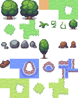
Let’s see this in action using the following water tiles. We’ll learn how constraints propagate to form a coherent environment:


Step 1 - Initial Grid
We start with an empty grid where every cell can potentially hold any tile. The ? symbols represent the “superposition” - each cell contains all possible tiles until we begin constraining them through the algorithm.
Step 2 - First Placement
The algorithm starts by placing the initial water center tile (almost). This placement immediately constrains the neighboring cells - they now know they need to connect to water on at least one side.
Step 3 - Propagate Constraints
Constraint propagation kicks in! The algorithm expands the water area by placing more center tiles, and the edge tiles are constrained to have water-facing sides where they connect to the water body.
Step 4 - Final Result
The algorithm completes by filling the edges with appropriate boundary tiles. Notice how each tile connects perfectly - center tiles have water on all sides, edge tiles have water facing inward and grass edges facing outward, creating a coherent geography.
This demonstrates the core Wave Function Collapse algorithm in action:
- Find the most constrained cell - the one with the fewest valid tiles that could fit
- Place a tile whose sockets are compatible with its neighbors
- Propagate constraints - this placement immediately reduces the valid options for surrounding cells
- Repeat until the grid is complete
When we hit a dead end (no valid tiles for a cell), our implementation takes a simpler approach than Sudoku: instead of backtracking through previous choices, we restart with a fresh random seed (up to a retry limit) and run the entire process again until we generate a valid map.
What do you mean by fresh random seed?
A “random seed” is a starting number that controls which “random” sequence the algorithm will follow. Same seed = same tile placement order every time. When we hit a dead end, instead of backtracking, we generate a new random seed and start over—this gives us a completely different sequence of tile choices to try.
Can configuring this randomness help us customize maps?
Yes! The algorithm’s randomness comes from the order in which it picks cells and tiles, and we can control this to influence the final result. By adjusting the random seed or the selection strategy, we can:
- Bias toward certain patterns - Weight certain tiles more heavily to create specific landscape types.
- Control size and complexity - Influence whether we get small ponds or large lakes.
- Create predictable variations - Use the same seed for consistent results, or different seeds for variety.
The same tileset can generate endless variations of coherent landscapes, from simple ponds to complex branching river systems, all by tweaking the randomness probability configuration.
- No large-scale structure control - WFC focuses on tile compatibility, so it won't automatically create big patterns like "one large lake" or "mountain ranges".
- Can get stuck - Complex rules might lead to impossible situations where no valid tiles remain, requiring restarts.
- Performance depends on complexity - More tile types and stricter rules increase computation time and failure rates.
- Requires careful rule design - Poorly designed compatibility rules can lead to unrealistic or broken landscapes.
From Theory to Implementation
Now that we understand how Wave Function Collapse works—the constraint propagation, socket compatibility, and tile placement logic—it’s time to transform this knowledge into actual running code.
The reality of implementation:
Building a WFC algorithm from scratch is complex. You’d need to implement:
- Constraint propagation across the entire grid
- Backtracking when hitting dead ends
- Efficient data structures for tracking possibilities
- Grid coordinate management
- Random selection with proper probability weights
That’s a lot of algorithmic complexity before we even get to the game-specific parts like sprites, rules, and world design.
Our approach:
Instead of reinventing the wheel, we’ll use a library that handles the WFC algorithm internals. This lets us focus on what makes our game unique: the tiles, the rules, the world aesthetics. We define what we want; the library figures out how to achieve it.
Setting Up Our Toolkit
Let’s add the procedural generation library to our project. We’ll be using the bevy_procedural_tilemaps crate, which I built by forking ghx_proc_gen library. I created this fork primarily to ensure compatibility with Bevy 0.17 and to simplify this tutorial.
If you need advanced features, check out the original ghx_proc_gen crate by Guillaume Henaux, which includes 3D capabilities and debugging tools.
Hope you are following the code from first chapter. Here’s the source code.
Update your Cargo.toml with the bevy_procedural_tilemaps crate.
[package]
name = "bevy_game"
version = "0.1.0"
edition = "2024"

[dependencies]
bevy = "0.17.2" // Line update alert
bevy_procedural_tilemaps = "0.1.2" // Line update alert
Bevy Procedural Tilemaps
The bevy_procedural_tilemaps library is a powerful tool that handles the complex logic of generating coherent, rule-based worlds.
What the Library Handles
The library takes care of the algorithmic complexity of procedural generation:
- Rule Processing: Converts our game rules into the library’s internal format.
- Generator Creation: Builds the procedural generation engine with our configuration.
- Constraint Solving: Figures out which tiles can go where based on rules.
- Grid Management: Handles the 2D grid system and coordinate transformations.
- Entity Spawning: Creates Bevy entities and positions them correctly.
What We Need to Provide
We need to give the library the game-specific information it needs:
- Sprite Definitions: What sprites to use for each tile type.
- Compatibility Rules: Which tiles can be placed next to each other.
- Generation Configuration: The patterns and constraints for our specific game world.
- Asset Data: Sprite information, positioning, and custom components.

How the System Works Together
The library pipeline works in stages: first it processes our rules and builds a generator, then the constraint solver figures out valid tile placements, and finally the entity spawner creates the actual game objects in the Bevy world.
The Workflow
- We Define: Create tile definitions, compatibility rules, and generation patterns
- Library Processes: Runs the constraint-solving algorithm to find valid tile placements
- Library Spawns: Creates Bevy entities with the correct sprites, positions, and components
- Result: A coherent, rule-based world appears in our game
The beauty of this system is that we focus on what we want (environment design), while the library handles how to achieve it (complex algorithms). This separation of concerns makes procedural generation accessible to game developers without requiring deep knowledge of constraint-solving algorithms.
What’s a generator?
A generator is the core engine that runs the procedural generation algorithm. It’s a puzzle solver that takes our rules (which tiles can go where) and our grid (the empty world), then systematically figures out how to fill every position with valid tiles. It uses constraint-solving algorithms to ensure that every tile placement follows our compatibility rules, creating a coherent world that makes sense according to our game’s logic.

Now that we understand how the procedural generation system works, let’s build our map module.
The Map Module
We’ll create a dedicated map folder inside the src folder to house all our world generation logic.
Why create a separate folder for map generation?
The map system is complex and requires multiple specialized components working together. World generation involves:
- Asset management - Loading and organizing hundreds of tile images.
- Rule definitions - Complex compatibility rules between different terrain types.
- Grid setup - Configuring map dimensions and coordinate systems.
Trying to fit all this logic into a single file would create a large file that can become difficult to navigate.
src/
├── main.rs
├── player.rs
└── map/
    ├── mod.rs
    ├── assets.rs
What’s mod.rs
The mod.rs file is Rust’s way of declaring what modules exist in a folder. It’s like the “table of contents” for our map module. Add the following line to your mod.rs.
// src/map/mod.rs
pub mod assets;   // Exposes assets.rs as a module
Why mod.rs specifically?
It’s Rust convention, when you create a folder, Rust looks for mod.rs to understand the module structure.
Building the Map System
Now that we’ve set up our module structure, we need to build the actual components. Our map system will consist of several interconnected files:
assets.rs- Defines what sprites to spawn and how to position themtilemap.rs- Maps sprite names to their pixel coordinates in our atlasmodels.rs- Organizes tile models and keeps them synchronized with their assetssockets.rs- Defines connection points for tile compatibilityrules.rs- Defines terrain layers, compatibility rules, and world generation logicgenerate.rs- Sets up the procedural generation engine
We’ll build these in a logical order, starting with the foundation and working our way up.
Creating SpawnableAsset
Let’s start by creating our assets.rs file inside the map folder. This will be the foundation that defines how we spawn sprites in our world.
The bevy_procedural_tilemaps library can generate complex worlds, but it needs to know what to actually place at each generated location.
Think about it: when the algorithm decides “this should be a grass tile,” it needs to know:
- Which sprite to use from our tilemap?
- Where exactly to position it?
- What components to add (collision, physics, etc.)?
The library expects us to provide this information in a very specific format. And doing this for every single tile type in your game - grass, dirt, trees, rocks, water, etc will result in redundant code.
This is where SpawnableAsset comes in. It’s our abstraction layer to help you avoid unnecessary boilerplate.
// src/map/assets.rs

use bevy::{prelude::*, sprite::Anchor};
use bevy_procedural_tilemaps::prelude::*;

#[derive(Clone)]
pub struct SpawnableAsset {
    /// Name of the sprite inside our tilemap atlas
    sprite_name: &'static str,
    /// Offset in grid coordinates (for multi-tile objects)
    grid_offset: GridDelta,
    /// Offset in world coordinates (fine positioning)
    offset: Vec3,
    /// Function to add custom components (like collision, physics, etc.)
    components_spawner: fn(&mut EntityCommands),
}
SpawnableAsset Struct
The SpawnableAsset struct contains all the information needed to spawn a tile in our world. The sprite_name field gives a name to your sprite (like “grass”, “tree”, “rock”).
The grid_offset is used for objects that span multiple tiles - it’s a positioning within the tile grid itself.
For example, a tree might need two tiles: the bottom part at the original position, and the top part one tile up. The offset field is for fine-tuning the position in world coordinates - this is for precise positioning adjustments.


Grid Offset
| Tree Part | Grid Offset | Description |
|---|---|---|
| Bottom-left | (0, 0) |
Stays at original position |
| Bottom-right | (1, 0) |
Moves one tile right |
| Top-left | (0, 1) |
Moves one tile up |
| Top-right | (1, 1) |
Moves one tile up and right |
The offset field, on the other hand, is for fine-tuning the position within the tile - like moving a rock slightly to the left or making sure a tree trunk is perfectly centered within its tile space.
Let’s see how offset works with rock positioning:


Offset
| Rock | Offset | Description |
|---|---|---|
| Rock 1 | (0, 0) |
Centered in tile |
| Rock 2 | (-8, -6) |
Moved slightly left and up |
| Rock 3 | (6, 5) |
Moved slightly right and down |
Finally, the components_spawner is a function that adds custom behavior like collision, physics, or other game mechanics.
Why is sprite name defined as &'static str?
To understand &'static str, we need to break down each part. Let’s start with the & symbol - this creates a reference to data instead of owning it. References are much more memory-efficient because they don’t copy the data, they just point to where it already exists.
Here’s how memory works with our sprite names:

The diagram shows two different memory areas: Stack (where our reference lives) and Read-only memory (where the actual string data is stored). The reference is just metadata that says “the string ‘grass’ is stored at this memory address.”
Our sprite name "grass" lives in read-only memory because it’s a string literal embedded in the compiled binary, while the reference &str lives on the stack because it’s just a fixed-size pointer (address + length) to that read-only data.

What’s a string literal?
A string literal is text that’s written directly in your code, surrounded by quotes. When you write "grass" in your Rust code, the compiler embeds this text directly into the compiled binary. This means:
- The text
"grass"becomes part of your executable file - It’s loaded into read-only memory when your program starts
- It exists for the entire duration of your program (hence
'staticlifetime) - Multiple references can point to the same literal without copying the text
What’s a lifetime and what has 'static got to do with it?
A lifetime is Rust’s way of tracking how long data lives in memory. Rust needs to know when it’s safe to use data and when it might be deleted.
Most data has a limited lifetime. For example:
- Local variables live only while a function runs
- Function parameters live only while the function executes
- Data created in a loop might be deleted when the loop ends
But some data lives forever - like string literals embedded in your program. The 'static lifetime means “this data lives for the entire duration of the program” - it never gets deleted.
This is perfect for our sprite names because they’re hardcoded in our source code (like "grass", "tree", "rock") and will never change or be deleted while the program runs. Rust can safely let us use these references anywhere in our code because it knows the data will always be there.
Why does Rust need to know when it’s safe to use data? Other languages don’t seem to care about this.
Most languages (like C, C++, Java, Python) handle memory safety differently:
- C/C++: Don’t track lifetimes at all - you can accidentally use deleted data, leading to crashes or security vulnerabilities
- Java/Python/C#: Use garbage collection - the runtime automatically deletes unused data, but this adds overhead and unpredictable pauses
- Rust: Tracks lifetimes at compile time - prevents crashes without runtime overhead
Here’s why this matters for game development:
The Problem Other Languages Have
// Psuedo code warning, don't use
// This would crash in C++ or cause undefined behavior
let sprite_name = {
    let temp = "grass";
    &temp  // temp gets deleted here!
};
println!("{}", sprite_name); // CRASH! Using deleted data
Rust Prevents This
Rust’s compiler analyzes your code and says “Hey, you’re trying to use data that might be deleted. I won’t let you compile this unsafe code.” This catches bugs before your game even runs.
Does str mean String data type?
Not quite. str represents text data, but you can only use it through a reference like &str (a view of text stored somewhere else). String is text you own and can modify. Our sprite names like “grass” are baked into the program, so &str just points to that text without copying it - much more efficient than using String.
Putting it all together
&'static str means “a reference to a string slice that lives for the entire program duration.” This gives us the best of all worlds: memory efficiency (no copying), performance (direct access), and safety (Rust knows the data will always be valid).
What’s GridDelta?
GridDelta is a struct that represents movement in grid coordinates. It specifies “how many tiles to move” in each direction. For example, GridDelta::new(1, 0, 0) means “move one tile to the right”, while GridDelta::new(0, 1, 0) means “move one tile up”. It’s used for positioning multi-tile objects like the tree sprite with multiple tiles we mentioned earlier in grid offset.
Why’s components_spawner defined as fn(&mut EntityCommands)?
This is a function pointer that takes a mutable reference to EntityCommands (Bevy’s way of adding components to entities). Looking at the code in assets.rs, we can see it defaults to an empty function that does nothing.
The function pointer allows us to customize what components get added to each spawned entity. For example, a tree sprite might need collision components for physics, while a decorative flower might only need basic rendering components. Each sprite can have its own custom set of components without affecting others.
Why do we need a mutable reference to EntityCommands?
Yes! In Rust, you need a mutable reference (&mut) when you want to modify something. EntityCommands needs to be mutable because it’s used to add, remove, or modify components on entities.
Now let’s add some helpful methods to our SpawnableAsset struct to make it easier to create and configure sprite assets.
Append the following code to the same assets.rs file.
// src/map/assets.rs
impl SpawnableAsset {
    pub fn new(sprite_name: &'static str) -> Self {
        Self {
            sprite_name,
            grid_offset: GridDelta::new(0, 0, 0),
            offset: Vec3::ZERO,
            components_spawner: |_| {}, // Default: no extra components
        }
    }

    pub fn with_grid_offset(mut self, offset: GridDelta) -> Self {
        self.grid_offset = offset;
        self
    }
}
What’s -> Self?
In Rust, you must specify the return type of functions (unlike some languages that can infer it). The -> Self tells the compiler exactly what type the function returns, which helps catch errors at compile time. Self means “the same type as the struct this method belongs to” - so Self refers to SpawnableAsset here.
What’s |_| {}?
This is a closure (anonymous function) that does nothing. The |_| means “takes one parameter but ignores it” (the underscore means we don’t use the parameter), and {} is an empty function body.
We need this because our SpawnableAsset struct requires a components_spawner field (as we saw in the struct definition), but for basic sprites we don’t want to add any custom components. This empty closure serves as a “do nothing” default. We’ll learn how to use this field to add custom components in later chapters, but for now it’s just a placeholder that satisfies the struct’s requirements.
What’s a closure? What do you mean by anonymous function?
A closure is a function that can “capture” variables from its surrounding environment. An anonymous function means it doesn’t have a name - you can’t call it directly like my_function(). Instead, you define it inline where you need it.
Variable capture example:
let health = 100;
let damage = 25;

// This closure captures 'health' and 'damage' from the surrounding scope
let attack = |_| {
    health - damage  // Uses captured variables
};
What this means:
- The closure
attack“remembers” the values ofhealthanddamagefrom when it was created - Even if
healthanddamagechange later, the closure still has the original values - The closure can use these captured variables when it’s called later.
Why use closures here?
Closures are perfect because they can capture game state (like player health, enemy types, or configuration settings) and use that information when spawning sprites. This allows each sprite to be customized based on the current game context.
Why is semicolon missing in the last line of these functions?
In Rust, the last expression in a function is automatically returned without needing a return keyword or semicolon. This makes it easier to specify what value should be returned - you just write the expression you want to return, and Rust handles the rest. This is Rust’s way of making code cleaner and more concise.
Why can’t you manipulate or retrieve grid_offset directly?
The fields are private (no pub keyword), which means they can only be accessed from within the same module. This is called “encapsulation” - it prevents developers from making mistakes by modifying the struct’s data directly, which could break the internal logic. We provide the public method with_grid_offset() to safely modify it while maintaining the struct’s integrity.
Now that we understand how to define our sprites with SpawnableAsset, how do we load and use these sprites in our game?
Loading Sprite Assets
Our game uses a sprite atlas - a single large image containing all our sprites. Bevy needs to know where each sprite is located within this image, and we need to avoid reloading the same image multiple times.
Create a folder tile_layers in your src/assets folder and place tilemap.png inside it, you can get it from the github repo.
Now inside src/map folder create a file tilemap.rs. When you add a file inside map folder, ensure to register it in mod.rs by adding the line pub mod tilemap.
This is where our tilemap definition comes in - it acts as a “map” that tells Bevy the coordinates of every sprite in our atlas.
// src/map/tilemap.rs
use bevy::math::{URect, UVec2};

pub struct TilemapSprite {
    pub name: &'static str,
    pub pixel_x: u32,
    pub pixel_y: u32,
}

pub struct TilemapDefinition {
    pub tile_width: u32,
    pub tile_height: u32,
    pub atlas_width: u32,
    pub atlas_height: u32,
    pub sprites: &'static [TilemapSprite],
}
The TilemapSprite struct represents a single sprite within our atlas. It stores the sprite’s name (like “dirt” or “green_grass”) and its exact pixel coordinates within the atlas image.
The TilemapDefinition struct serves as the “blueprint” that Bevy uses to understand how to slice up our atlas image into individual sprites.
Though our tilemap stores sprite names and pixel coordinates, Bevy’s texture atlas system requires numeric indices and rectangular regions. These methods perform the necessary conversions.
Append the following code to your tilemap.rs.
// src/map/tilemap.rs

impl TilemapDefinition {
    pub const fn tile_size(&self) -> UVec2 {
        UVec2::new(self.tile_width, self.tile_height)
    }

    pub const fn atlas_size(&self) -> UVec2 {
        UVec2::new(self.atlas_width, self.atlas_height)
    }

    pub fn sprite_index(&self, name: &str) -> Option<usize> {
        self.sprites.iter().position(|sprite| sprite.name == name)
    }

    pub fn sprite_rect(&self, index: usize) -> URect {
        let sprite = &self.sprites[index];
        let min = UVec2::new(sprite.pixel_x, sprite.pixel_y);
        URect::from_corners(min, min + self.tile_size())
    }
}
The tile_size() method converts our tile dimensions into a UVec2 (unsigned 2D vector), which Bevy uses for size calculations. Similarly, atlas_size() provides the total atlas dimensions as a UVec2, which Bevy uses to create the texture atlas layout.
The sprite_index() method is crucial for finding sprites by name. When we want to render a “dirt” tile, this method searches through our sprite array and returns the index position of that sprite.
Finally, sprite_rect() takes a sprite index and calculates the exact rectangular region within our atlas that contains that sprite. It uses URect (unsigned rectangle) to define the boundaries, which Bevy’s texture atlas system requires to know which part of the large image to display.
Now let’s put our tilemap definition to use by adding our first sprite - the dirt tile.
Adding the dirt tile
Let’s start with a simple dirt tile to test our tilemap system. We’ll add more sprites later as we build out our game world.
Append this code to tilemap.rs
// src/map/tilemap.rs
pub const TILEMAP: TilemapDefinition = TilemapDefinition {
    tile_width: 32,
    tile_height: 32,
    atlas_width: 256,
    atlas_height: 320,
    sprites: &[
          TilemapSprite {
            name: "dirt",
            pixel_x: 128,
            pixel_y: 0,
        },
    ]
};
Perfect! We now have a complete tilemap definition with our first sprite. Notice how we’re using a const definition - this means all this sprite metadata is determined at compile time, making it very efficient. The dirt tile sits at pixel coordinates (128, 0) in our 256x320 atlas image.
Connecting the Tilemap to Asset Loading
Now that we’ve defined our tilemap and sprites in tilemap.rs, we need to connect this to our asset loading system in assets.rs. tilemap.rs knows where each sprite is in our atlas from disk, while assets.rs will handle loading the atlas and converting these coordinates into actual renderable sprites.
Let’s update the imports in assets.rs to bring in our TILEMAP definition:
// src/map/assets.rs
use bevy::prelude::*;
use bevy_procedural_tilemaps::prelude::*;
use crate::map::tilemap::TILEMAP; // <--- line update alert
With the import in place, we can now build the three key functions that helps our procedural rendering system:
TilemapHandles- Container that holds our loaded atlas and layout dataprepare_tilemap_handles- Loads the atlas image from disk and builds the layout structureload_assets- Converts sprite names intoSpritedata structures ready for rendering
Let’s build these step by step.
Step 1: Creating the TilemapHandles Struct
First, we need a way to hold references to both the atlas image and its layout. Go ahead and append this code into your assets.rs:
// src/map/assets.rs
#[derive(Clone)]
pub struct TilemapHandles {
    pub image: Handle<Image>,
    pub layout: Handle<TextureAtlasLayout>,
}

impl TilemapHandles {
    pub fn sprite(&self, atlas_index: usize) -> Sprite {
        Sprite::from_atlas_image(
            self.image.clone(),
            TextureAtlas::from(self.layout.clone()).with_index(atlas_index),
        )
    }
}
What’s happening here:
The TilemapHandles struct is a container for two handles: image points to our loaded sprite sheet file, while layout points to the atlas layout that tells Bevy how to slice that image into individual sprites.
The sprite(atlas_index) method is a convenience function that creates a ready-to-render Sprite by combining the image and layout with a specific index. For example, if the dirt tile is at index 0, calling tilemap_handles.sprite(0) gives us a Sprite configured to display just the dirt tile from our atlas.
Step 2: Loading the Atlas from Disk
Now let’s create the function that actually loads the atlas image file and sets up the layout. This is where the connection to our TILEMAP definition becomes crucial.
pub fn prepare_tilemap_handles(
    asset_server: &Res<AssetServer>,
    atlas_layouts: &mut ResMut<Assets<TextureAtlasLayout>>,
    assets_directory: &str,
    tilemap_file: &str,
) -> TilemapHandles {
    let image = asset_server.load::<Image>(format!("{assets_directory}/{tilemap_file}"));
    let mut layout = TextureAtlasLayout::new_empty(TILEMAP.atlas_size());
    for index in 0..TILEMAP.sprites.len() {
        layout.add_texture(TILEMAP.sprite_rect(index));
    }
    let layout = atlas_layouts.add(layout);

    TilemapHandles { image, layout }
}
Breaking it down:
- Load the image:
asset_server.load()requests the atlas image file from disk - Create empty layout:
TextureAtlasLayout::new_empty(TILEMAP.atlas_size())creates a layout matching our 256x320 atlas - Register each sprite: The loop iterates through all sprites in
TILEMAP, usingTILEMAP.sprite_rect(index)to get each sprite’s coordinates and adding them to the layout - Store and return: The layout is added to Bevy’s asset system, and we return a
TilemapHandlescontaining both handles
This is where TILEMAP.atlas_size() and TILEMAP.sprite_rect() from our tilemap definition come into play - they tell Bevy exactly how to slice up our atlas image!
Step 3: Converting Sprite Names to Renderable Sprites
Finally, we need a way to convert sprite names (like “dirt”) into actual Sprite objects that can be rendered. This is the last piece that connects everything we’ve built so far.
pub fn load_assets(
    tilemap_handles: &TilemapHandles,
    assets_definitions: Vec<Vec<SpawnableAsset>>,
) -> ModelsAssets<Sprite> {
    let mut models_assets = ModelsAssets::<Sprite>::new();
    for (model_index, assets) in assets_definitions.into_iter().enumerate() {
        for asset_def in assets {
            let SpawnableAsset {
                sprite_name,
                grid_offset,
                offset,
                components_spawner,
            } = asset_def;

            let Some(atlas_index) = TILEMAP.sprite_index(sprite_name) else {
                panic!("Unknown atlas sprite '{}'", sprite_name);
            };

            models_assets.add(
                model_index,
                ModelAsset {
                    assets_bundle: tilemap_handles.sprite(atlas_index),
                    grid_offset,
                    world_offset: offset,
                    spawn_commands: components_spawner,
                },
            )
        }
    }
    models_assets
}
Why the two loops?
Some tiles are simple and need just one sprite (like dirt). Others are complex and need multiple sprites (like a tree that needs 4 parts).
The outer loop says “for each type of tile,” and the inner loop says “for each sprite that tile needs.”
Let’s walk through what happens when we load a dirt tile:
- We have:
SpawnableAsset { sprite_name: "dirt", ... } - The function asks TILEMAP: “Where is ‘dirt’?” → TILEMAP replies: “Index 0”
- It then asks TilemapHandles: “Give me a Sprite for index 0” → Gets back a ready-to-render
Sprite - Finally, it packages everything together with the positioning info and stores it
What does the final data look like?
After load_assets completes, we have a collection of ModelAsset objects in memory. Here’s what the data structure looks like for a few tiles:
| Model | Field | Value | What It Means |
|---|---|---|---|
| Dirt | assets_bundle |
Sprite(atlas_index: 0) |
Points to dirt sprite in atlas |
grid_offset |
(0, 0, 0) |
No grid offset needed | |
world_offset |
(0, 0, 0) |
No world offset needed | |
| Tree (bottom) | assets_bundle |
Sprite(atlas_index: 31) |
Points to tree bottom sprite |
grid_offset |
(0, 0, 0) |
Placed at base position | |
world_offset |
(0, 0, 0) |
Centered | |
| Tree (top) | assets_bundle |
Sprite(atlas_index: 30) |
Points to tree top sprite |
grid_offset |
(0, 1, 0) |
One tile up from bottom | |
world_offset |
(0, 0, 0) |
Centered |
Important: These are just data structures in memory - nothing is drawn on screen yet! The actual rendering happens later when the procedural generator uses these prepared ModelAsset objects to spawn entities.
From Tiles to Models
We now have assets that know how to render tiles. But the procedural generator needs to know which tiles can be placed next to which.
You already understand tiles - the individual visual pieces like grass, dirt, and water. Now we need to add sockets to these tiles and define connection rules so the generator can figure out valid placements.
Models = Tiles + Sockets
A two-step process:
- Create model with socket labels (which side has which socket)
- Separately define connection rules (which sockets can connect)
How Models Expose Sockets
Models expose sockets - labeled connection points on each edge. Let’s look at a green grass tile and see how it exposes sockets in different directions.
Horizontal Plane (x and y directions)
grass.material
grass.material
GRASS
grass.material
grass.material
Vertical Axis (z direction)
grass.layer_up
GRASS
grass.layer_down
How does z-axis make sense in a 2D game?
Even though we’re building a 2D game, the z-axis represents layering - Imagine stacking transparent sheets on top of each other. Here’s how it works with our yellow grass example:
The Layering System:
- Dirt tiles form the base layer (ground level)
- Green grass tiles can sit on top of dirt (one layer up)
- Yellow grass tiles can sit on top of green grass (another layer up)
With multiple layers like dirt, grass, and yellow grass, we need a way to keep our models and their corresponding sprites organized.
Keeping Models and Sprites in Sync
The WFC algorithm needs to know the placement rules (models), while the renderer needs to know which sprites to draw (assets).
The challenge is that these are stored in separate collections that must stay synchronized by index:
// Models and assets must stay aligned by index
let mut models = ModelCollection::new();
let mut assets = Vec::new();

models.create(dirt_template);     // Model 0
assets.push(vec![SpawnableAsset::new("dirt")]);  // Asset 0 ✓

models.create(grass_template); // Model 1
assets.push(vec![SpawnableAsset::new("grass")]); // Asset 1 ✓
If these lists get out of sync, the generator will place the wrong sprites or crash entirely. We need a system that keeps them together.
The TerrainModelBuilder
Create a new file models.rs inside the map folder, and don’t forget to add pub mod models; to your mod.rs.
// src/map/models.rs
use bevy_procedural_tilemaps::prelude::*;
use crate::map::assets::SpawnableAsset;

/// Utility wrapper that ensures model declarations and their asset bindings stay aligned.
pub struct TerrainModelBuilder {
    pub models: ModelCollection<Cartesian3D>,
    pub assets: Vec<Vec<SpawnableAsset>>,
}
The TerrainModelBuilder holds both lists in one place:
models: What the WFC algorithm usesassets: The sprites for each model
By bundling them together, you can’t add one without the other. Problem solved!
Now let’s add the methods that make this builder useful:
// src/map/models.rs
impl TerrainModelBuilder {
    pub fn new() -> Self {
        Self {
            models: ModelCollection::new(),
            assets: Vec::new(),
        }
    }

    pub fn create_model<T>(
        &mut self,
        template: T,
        assets: Vec<SpawnableAsset>,
    ) -> &mut Model<Cartesian3D>
    where
        T: Into<ModelTemplate<Cartesian3D>>,
    {
        let model_ref = self.models.create(template);
        self.assets.push(assets);
        model_ref
    }

    pub fn into_parts(self) -> (Vec<Vec<SpawnableAsset>>, ModelCollection<Cartesian3D>) {
        (self.assets, self.models)
    }
}
The TerrainModelBuilder provides three simple methods that solve our synchronization problem. The new() method creates an empty builder to start with.
The create_model() method both a socket definition and the corresponding sprites, then adds them to their respective collections at the same index, making it impossible to mismatch them.
Finally, into_parts() splits the builder back into separate collections when you’re done building, so the assets can go to the renderer and the models can go to the WFC generator. This simple wrapper prevents us from making “wrong sprite for wrong model” mistakes.
What’s <T> doing in pub fn create_model<T>?
The <T> is Rust’s generic type parameter - it’s like a placeholder that gets filled in with the actual type when you call the function. In our case, we might pass in different types of socket definitions (like simple single-socket tiles or complex multi-socket tiles), but we want to perform the same operation on all of them.
Generics let us write one function that works with multiple types, as long as they can all be converted into a ModelTemplate. This is incredibly powerful because it means we can add new socket definition types in the future without changing our TerrainModelBuilder code - the compiler will automatically handle the type conversions for us!
What’s this where T: Into<ModelTemplate<Cartesian3D>>?
This is a trait bound that tells Rust what capabilities the generic type T must have. The where clause says “T must be able to convert itself into a ModelTemplate<Cartesian3D> (a 3D model template).”
Into is Rust’s way of saying “this type knows how to transform itself into that type” - like how a string can be converted into a number, or how our socket definitions can be converted into model templates. This means we can pass in any type that knows how to become a ModelTemplate - whether it’s simple single-socket tiles, complex multi-socket tiles, or even a custom socket type you create later.
Rust automatically provides this conversion ability for compatible types, so this gives us maximum flexibility while ensuring type safety. The compiler will catch any attempts to pass in a type that can’t be converted, preventing runtime errors!
Building the Foundation: Dirt Layer Sockets
Now that we understand how to keep models and assets synchronized, let’s start building our procedural world from the ground up - literally! The dirt layer forms the foundation that everything else sits on.
Why Layers Make WFC Simpler:
Without layers, we’d need to cram all our rules into a single layer: “water connects to water and grass”, “grass connects to grass and dirt”, “trees connect to grass”, “dirt connects to dirt” - plus all the edge cases and special connections. This creates a massive web of interdependencies that makes the WFC algorithm struggle to find valid solutions.
By using layers, we break this complexity into manageable pieces. Each layer only needs to worry about its own connections, making the WFC algorithm much more likely to find valid solutions quickly.
Let’s see how this works in practice by examining our dirt layer implementation:
Create a new file sockets.rs inside the map folder, and don’t forget to add pub mod sockets; to your mod.rs.
// src/map/sockets.rs
use bevy_procedural_tilemaps::prelude::*;

pub struct TerrainSockets {
    pub dirt: DirtLayerSockets,
}
pub struct DirtLayerSockets {
    pub layer_up: Socket,      // What can sit on top of dirt
    pub layer_down: Socket,     // What dirt can sit on
    pub material: Socket,       // What dirt connects to horizontally
}
Understanding Dirt’s Socket System:
The dirt layer needs three types of sockets to function properly in our 3D world:
-
layer_up- This socket defines what can be placed in the layer above dirt. Remember layers are to seperate rule cram concerns (water can be above grass without touching it). -
layer_down- This socket defines what layer the dirt itself can be placed on. For the base layer, this will connect to void (empty space). -
material- This socket handles horizontal connections between dirt tiles, ensuring they connect properly to form continuous ground.
Creating the Rules: Building the Dirt Layer
Now that we have our socket system defined, we need to create the rules that tell the WFC algorithm how to use these sockets. This is where we define what tiles can be placed and how they connect to each other.
Create a new file rules.rs inside the map folder, and don’t forget to add pub mod rules; to your mod.rs.
// src/map/rules.rs
use crate::map::assets::SpawnableAsset;
use crate::map::models::TerrainModelBuilder;
use crate::map::sockets::*;
use bevy_procedural_tilemaps::prelude::*;

fn build_dirt_layer(
    terrain_model_builder: &mut TerrainModelBuilder,
    terrain_sockets: &TerrainSockets,
    socket_collection: &mut SocketCollection,
) {
    terrain_model_builder
        .create_model(
            SocketsCartesian3D::Simple {
                x_pos: terrain_sockets.dirt.material,
                x_neg: terrain_sockets.dirt.material,
                z_pos: terrain_sockets.dirt.layer_up,
                z_neg: terrain_sockets.dirt.layer_down,
                y_pos: terrain_sockets.dirt.material,
                y_neg: terrain_sockets.dirt.material,
            },
            vec![SpawnableAsset::new("dirt")],
        )
        .with_weight(20.);

    socket_collection.add_connections(vec![(
        terrain_sockets.dirt.material,
        vec![terrain_sockets.dirt.material],
    )]);
}
Understanding the Dirt Layer Rules:
- Creates a dirt model - Defines a tile that exposes sockets on all six sides
- Exposes socket types - Horizontal sides expose
dirt.material, vertical sides expose layer sockets - Assigns a sprite -
SpawnableAsset::new("dirt")tells the renderer which sprite to use - Sets the weight -
.with_weight(20.)makes dirt tiles 20 times more likely to be placed - Defines connection rules -
add_connectionstells WFC thatdirt.materialcan connect to otherdirt.material
This creates a simple but effective foundation layer that can form continuous ground while supporting other layers on top!
Now we need a function that the generator will call to get all our dirt layer rules and models:
pub fn build_world() -> (
    Vec<Vec<SpawnableAsset>>,
    ModelCollection<Cartesian3D>,
    SocketCollection,
) {
    let mut socket_collection = SocketCollection::new();
    let terrain_sockets = create_sockets(&mut socket_collection);

    let mut terrain_model_builder = TerrainModelBuilder::new();

    // Build dirt layer
    build_dirt_layer(
        &mut terrain_model_builder,
        &terrain_sockets,
        &mut socket_collection,
    );

    let (assets, models) = terrain_model_builder.into_parts();

    (assets, models, socket_collection)
}
What This Function Does:
- Creates the socket collection - This is where all our socket connection rules are stored
- Gets our socket definitions - Calls
create_sockets()to get all the socket types we defined - Creates the model builder - This keeps our models and assets synchronized
- Builds the dirt layer - Calls our
build_dirt_layerfunction to create all the dirt models and rules - Returns the three collections - Assets for rendering, models for WFC rules, and socket collection for connections
This function is what the generator calls to get all the rules and models needed to create our procedural world!